
Why Choose Transformer Switch Gear for Power Systems?
Transformer Switch Gear helps protect the connection between a transformer and the wider power system. It can isolate equipment during maintenance and interrupt faults when correctly selected and coordinated. In a substation, that may mean a breaker opening before a fault damages a transformer winding or interrupts service across an entire feeder. The benefit is practical, not automatic. Ratings, protection settings, and installation conditions must match the system.
Choosing suitable equipment requires more than comparing voltage labels. Engineers review rated current, short-circuit capacity, insulation levels, switching duties, and the transformer’s protection scheme. They also consider whether the installation is indoors or outdoors, how often switching occurs, and whether technicians can inspect components safely. A compact design may save space, yet leave less room for access or future upgrades. That matters.
Reliable decisions depend on verified manufacturer data, applicable technical standards, and site-specific engineering review. Maintenance plans deserve equal attention: contact wear, insulation condition, operating mechanisms, and environmental exposure can affect performance over time. No system is perfect. Even well-designed switchgear can underperform if settings are poorly coordinated or maintenance is delayed. Understanding these trade-offs helps utilities, facility operators, and project teams assess where Transformer Switch Gear fits, what protection it provides, and which questions to resolve before specifying it.
What Transformer Switchgear Is and How It Works
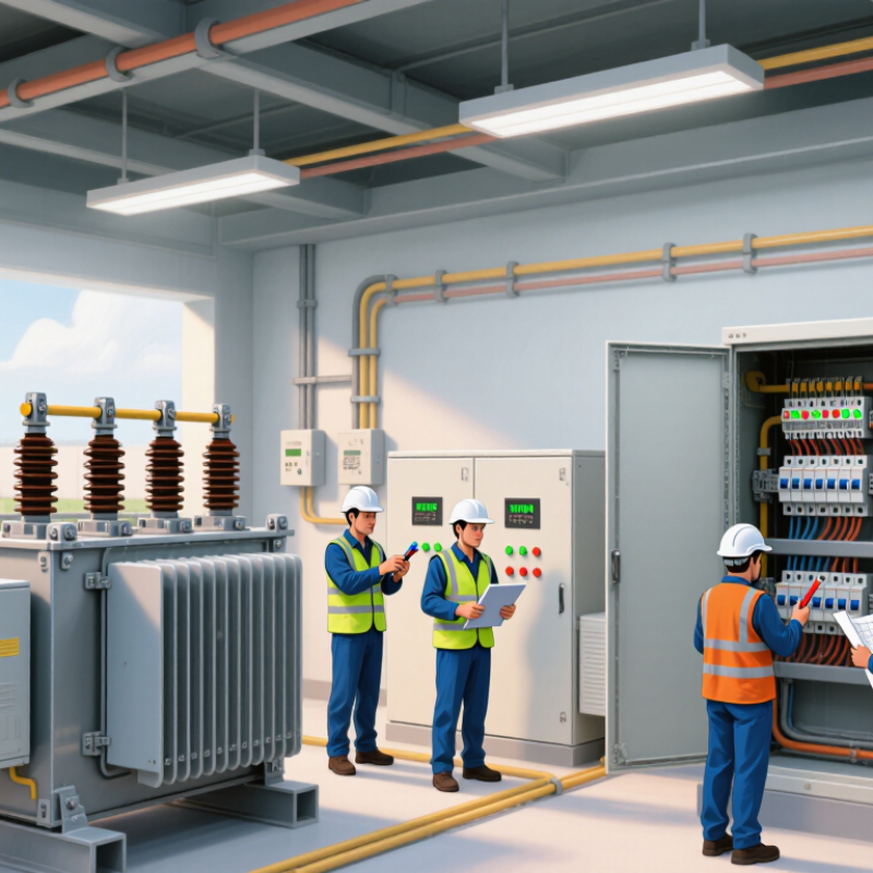
Transformer switchgear is the equipment that connects a power transformer to the electrical network and helps control and protect that connection. It may sit beside the transformer or form part of a coordinated substation arrangement. A transformer changes voltage levels; the switchgear handles switching and fault protection. It typically includes circuit breakers, isolators, protective relays, and current or voltage sensors.
If a fault causes excessive current, sensors send information to a protective relay. The relay signals the circuit breaker to open, interrupting the affected circuit and limiting damage to equipment. That matters. For maintenance, operators can isolate sections after the appropriate switching steps, reducing exposure to energized parts. The exact sequence depends on the system design and operating procedures.
A typical installation uses high-voltage equipment on the transformer’s incoming side and lower-voltage switchgear on its outgoing side. The ratings, insulation, and protection settings must match the transformer and expected network conditions. Choosing suitable switchgear can support safer, more reliable operation, but equipment selection alone cannot prevent every outage. The layout, testing, and maintenance plan matter too. Not always obvious. Even a correctly rated breaker may not provide adequate protection if relay settings or coordination are poorly designed.
Key Components of a Transformer Switchgear System
A transformer switchgear system connects a transformer to the circuits it serves while helping control faults and isolate equipment. Its main components include the transformer, circuit breakers, disconnectors, protective relays, and instrument transformers. Each has a distinct job. Together, they make power distribution easier to monitor and maintain.
The transformer changes voltage to suit the system. Circuit breakers interrupt current when a fault occurs, while disconnectors provide a visible isolation point for maintenance. They are not interchangeable: a disconnector is generally not designed to break fault current. Protective relays read signals from current and voltage transformers, then tell the breaker when conditions exceed set limits. Small details matter.
Busbars carry power between components, and surge arresters help limit damaging voltage spikes. Grounding paths give fault current a safer route and support protective operation. Enclosures also matter; their ratings should match the site’s dust, moisture, and temperature conditions. In practice, coordination between relays and breakers deserves careful review. It can be overlooked when attention stays on the transformer alone. That can happen. A poorly placed sensor or unclear maintenance access may complicate testing later, even if the equipment performs well during normal operation.
How Switchgear Protects and Controls Power Systems
Why Choose Transformer Switch Gear for Power Systems?
How Switchgear Protects and Controls Power Systems
In a transformer installation, switchgear does more than connect cables. Circuit breakers interrupt fault current, while protective relays detect abnormal conditions and trigger isolation. This limits damage to transformers, busbars, and downstream equipment. Operators can isolate one section for inspection while other circuits remain energized, when system design permits. That detail matters during a wet, noisy maintenance shift.
The International Energy Agency’s 2023 report, Electricity Grids and Secure Energy Transitions, says annual grid investment must exceed USD 600 billion by 2030 in its net-zero pathway. As grids expand, dependable switching and protection become increasingly important. Switchgear ratings and relay settings must suit transformer impedance and expected fault levels. A mismatch can cause unnecessary trips or leave equipment exposed. Field conditions are not always as tidy as design drawings suggest.
Tips: Check voltage, continuous-current, and short-circuit ratings against current study results. Test relay coordination and breaker operation on a planned schedule. Keep clear access around panels, label isolation points, and record setting changes. Small omissions matter. A sound installation still depends on careful commissioning and maintenance.
Benefits of Choosing Transformer Switchgear
Choosing transformer switchgear can simplify power distribution by combining a transformer with switching and protective equipment in one coordinated assembly. Fewer separate connections can mean a tidier installation and less cable routing between components. In a compact electrical room, that space can matter. It may also make routine inspection easier when access points are planned carefully.
Protection coordination is another practical benefit. Properly selected equipment can help isolate a fault and limit disruption to other parts of a system. For example, engineers consider transformer capacity, expected fault current, load patterns, and the available supply before choosing ratings. The details matter. A unit that looks suitable on a drawing may need more clearance for ventilation or maintenance once installed. That trade-off is easy to underestimate.
Integrated equipment can reduce installation complexity, but it does not remove the need for sound design. Operators still need clear labels, safe working space, and a maintenance plan that fits the site. Conditions change, too: future loads may exceed the original estimate. Reviewing expansion needs early can prevent a compact solution from becoming awkward later.
Factors to Consider When Selecting Transformer Switchgear
Selecting transformer switchgear begins with the transformer’s rated voltage, capacity, and connection details. Confirm continuous-current and short-circuit ratings against the system study, not just the expected load. Check the nameplate. The equipment must withstand likely fault levels and coordinate with upstream and downstream protection. A mismatch can expose the transformer or cause unnecessary outages.
Insulation level and switching duty matter too. Consider whether the installation is indoors or outdoors, along with dust, moisture, altitude, temperature, and available clearance. For example, a coastal room may need greater corrosion protection than a clean indoor substation. Verify cable entries, bus connections, earthing, and space for safe inspection. Small details matter. Maintenance access is easy to underestimate on a drawing.
Review relay functions, instrument-transformer ratios, and communication needs with the protection engineer. Confirm that trip settings account for transformer inrush and downstream faults; generic settings can be misleading. Allow for future load growth, but check fault duty, footprint, and operating cost before choosing larger equipment. Document the assumptions, then have a qualified electrical engineer verify the design against applicable standards and site conditions.
Why Choose Transformer Switch Gear for Power Systems? - Factors to Consider When Selecting Transformer Switchgear
| Selection factor | What to check | Practical guidance | Why it matters |
|---|---|---|---|
| System voltage | Nominal system voltage and the switchgear’s rated voltage and insulation levels. | Match the equipment to the system design and applicable insulation requirements. Medium-voltage metal-enclosed switchgear is covered by IEC 62271-200 for rated voltages above 1 kV and up to 52 kV. | Equipment with unsuitable voltage or insulation ratings may not withstand normal operating stresses or transient overvoltages. |
| Transformer load current | Transformer kVA rating, winding voltage, phase configuration, and expected load profile. | For a three-phase transformer, estimate line current using I = S ÷ (√3 × V), where S is apparent power in VA and V is line-to-line voltage in volts. Select continuous-current ratings with the project’s loading and ambient conditions in mind. | Correct current sizing helps prevent excessive heating and supports reliable operation at the transformer’s intended load. |
| Short-circuit withstand and interruption | Prospective fault current at the installation point, fault duration, and the equipment’s making, breaking, and short-time withstand ratings. | Use a system fault study to establish required ratings, then confirm that the switchgear and protective devices are coordinated with the transformer and upstream network. | Fault levels depend on the network and transformer impedance; ratings should not be selected from transformer capacity alone. |
| Protection and switching arrangement | Required protection functions, operating frequency, remote-control needs, and the consequences of a fault. | A fused switch may suit some transformer-feeder applications; a circuit breaker with relays may be preferable where adjustable protection, repeated switching, or more detailed monitoring is required. Verify coordination with upstream and downstream devices. | The appropriate arrangement depends on system design, utility requirements, protection study results, and operating procedures. |
| Switchgear construction | Available space, installation location, access, and maintenance strategy. | Air-insulated equipment can be suitable where space and environmental protection are adequate. Gas-insulated or other sealed designs can reduce footprint, but their operating and maintenance requirements should be assessed. | Construction affects footprint, installation layout, service access, and the procedures needed over the equipment’s life. |
| Indoor or outdoor environment | Ambient temperature, humidity, dust, altitude, corrosion, water exposure, and enclosure requirements. | Confirm the specified service conditions and enclosure protection for the actual site. Apply any required derating or design provisions identified by the project and equipment documentation. | Site conditions can affect insulation performance, cooling, corrosion resistance, and safe access. |
| Safety and access | Interlocking, earthing provisions, internal-arc requirements, operating position, and access control. | Specify safety features based on the installation risk assessment, applicable regulations, and operating procedures. Where internal-arc classification is required, confirm the relevant test classification and installation conditions. | Safety depends on equipment design as well as installation, maintenance, and correct operating practices. |
| Standards and compatibility | Applicable local rules, utility specifications, interface dimensions, cable termination, and control-system requirements. | Check the relevant product standards for the equipment type, such as IEC 62271 for high-voltage switchgear and controlgear, and IEC 60076 for power transformers. Confirm all project-specific interfaces before ordering. | Compliance and interface checks support safe integration and help avoid installation delays or incompatible connections. |
| Lifecycle and serviceability | Inspection intervals, spare parts, maintenance access, monitoring, and end-of-life handling. | Compare the documented maintenance plan and total lifecycle needs, not only initial purchase cost. Confirm the availability of service support and required operating tools. | A suitable lifecycle plan can improve maintainability and help manage ownership costs and equipment availability. |
Note: Final equipment ratings and configuration should be determined from the project’s load, fault, protection, environmental, and applicable regulatory requirements.
