How to Choose the Right Powerline Transformer?
Choosing the right Powerline Transformer starts with the job it must perform. A nameplate rating alone cannot tell the whole story. The load profile, voltage levels, installation location, and expected growth all matter. A unit serving a rural feeder may face different demands from one near a dense industrial site.
Power engineering scholar George G. Karady has contributed to the field through research and technical publications. To avoid inventing a quotation, the following is an editorial paraphrase, not his verbatim words: “Select the transformer for the system’s real operating conditions, not just its rated capacity.” That principle keeps attention on practical details. Consider the highest expected load, daily demand swings, cooling method, insulation, and protection requirements. Check the available space, too. A transformer that fits electrically may still be difficult to install or maintain.
Good selection also depends on reliable data. Gather load measurements, fault levels, site conditions, and the utility’s requirements before comparing specifications. Then review efficiency, losses, noise, and maintenance needs with qualified power professionals. Small details matter: a hot enclosure, limited access, or a misleading load forecast can change the decision. Some assumptions will still be imperfect. State them clearly, test their impact, and revisit them when better measurements arrive. A sound choice balances present needs with safe, dependable operation over the equipment’s service life.
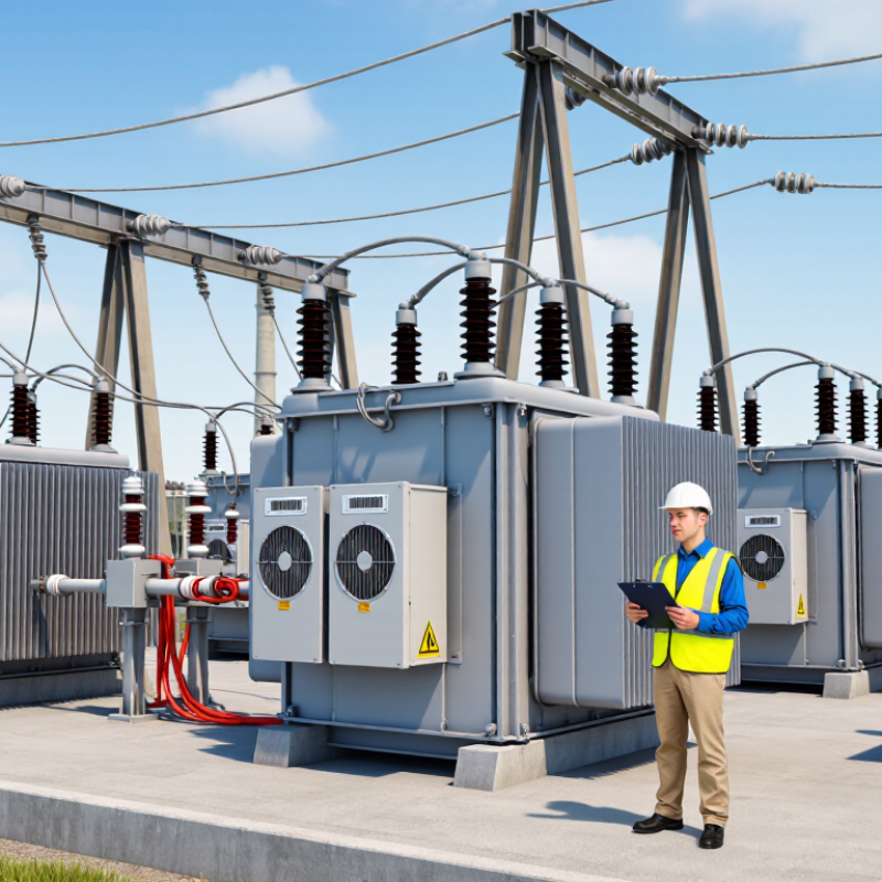
Define Peak Load and Load Profile Before Choosing a Transformer Rating
How to Choose the Right Powerline Transformer?
Define the peak load before selecting a transformer rating. Add the loads expected to operate at the same time, not every device’s nameplate rating. Then examine the load profile: hourly demand, seasonal changes, motor-starting surges, and how long peaks last.
A brief spike does not create the same thermal stress as several hours near full load. Check the measurement interval, too; a monthly bill can hide short, sharp peaks. That is easy to miss.
The wider grid shows why annual energy is not enough. The U.S. Energy Information Administration’s 2023 Electric Power Annual reports about 4,178 billion kWh of net generation, but that total cannot reveal the peak on one local feeder. NERC’s 2024 Long-Term Reliability Assessment projects North American summer peak demand growth of about 132 GW over the next decade.
Local conditions still matter more for an individual transformer. Compare measured peak kVA with the expected operating profile, ambient temperature, and planned load growth. Allow for credible growth, but avoid oversizing based on vague hopes; lightly loaded equipment can add unnecessary cost and losses. Forecasts are imperfect. Recheck assumptions against interval-meter data and actual operating schedules before approving the rating.
Match Primary and Secondary Voltages to System Levels (e.g., 12.47/0.48 kV)
Choosing the right powerline transformer starts with matching its primary and secondary voltages to the actual system. A 12.47/0.48 kV rating generally means a 12.47 kV primary and a 480 V secondary, often for a three-phase distribution system. Confirm whether the stated voltages are line-to-line or line-to-neutral; confusing them can lead to the wrong connection or equipment selection. Check the utility’s nominal primary voltage and the facility’s required service voltage, not just the nearest figures on a drawing. A voltage label alone is not enough.
Tips: Verify phase count, winding configuration, and grounding requirements with the utility or a qualified engineer. For example, a 480 V wye secondary may provide a neutral, while another configuration may not. Review available tap settings for small adjustments, but do not use taps to compensate for a fundamentally mismatched system.
Even a correct voltage ratio can be a poor fit if the load, starting current, or future expansion is overlooked. Compare the expected load with the transformer’s rating and confirm that protective equipment suits both voltage levels. This check can feel repetitive, yet it catches practical errors. One detail that is easy to miss is whether the listed 480 V is the voltage the connected equipment actually needs. Recheck the site documents before ordering; they are not always perfectly consistent.
Calculate Three-Phase Capacity: kVA = √3 × V × A ÷ 1,000
For a three-phase transformer, estimate apparent power with kVA = √3 × line-to-line voltage × line current ÷ 1,000. At 480 V and 100 A, the load is about 83.1 kVA. That is a working estimate, not a final rating. Check that voltage and current readings represent the same operating condition, and confirm whether the load is continuous.
Allow for measured peak demand, motor starting current, harmonics, ambient temperature, and planned load growth. The U.S. Energy Information Administration reports that transmission and distribution losses have averaged about 5% in recent years. That figure describes the wider grid; it is not a transformer-sizing allowance. Use the equipment nameplate and applicable engineering guidance, and have a qualified professional verify the selection. Small details matter. I have seen a neat calculation miss a short, heavy startup.
Tips: Record voltage and current during the busiest operating period. Compare the calculated kVA with the transformer’s rated capacity, then check thermal limits and manufacturer data. Avoid adding a blanket oversizing margin without checking actual conditions.
Check Impedance Against Utility Requirements; 5.75% Is a Common Standard Value
When selecting a powerline transformer, treat impedance as a system requirement, not a catalog preference. A value of 5.75% is common for some utility distribution transformers, but it is not a universal target. Check the utility’s current specification and project documents before comparing units. Small differences matter.
Percent impedance describes the voltage needed to drive rated current through a transformer under test conditions. It also helps determine available fault current and influences voltage drop under load. For example, lower impedance can increase fault current, so protection settings and equipment ratings must be reviewed together. Ask the utility to confirm acceptable tolerances, test basis, and whether the stated value applies to the selected kVA rating and winding configuration. Read the nameplate and factory test report; do not rely on a sales description alone.
Record the specified and measured impedance, then flag any mismatch before energization. A 5.75% unit may suit one feeder and fail another. That can be inconvenient. Utility drawings can be outdated, and a familiar value does not settle the question. Confirm requirements with the responsible utility engineer, especially when replacing an existing transformer or coordinating protective devices. Keep written approval with the procurement records.
Verify Temperature Rise and Compliance with IEEE C57.12.00 or IEC 60076
How to Choose the Right Powerline Transformer?
Temperature rise is a key check when selecting a powerline transformer. It shows how much hotter the oil and windings become than the surrounding air under specified operating conditions. A transformer may appear suitable on paper, yet struggle at a hot, dusty site. Small details matter. Review whether test results match the rated load, cooling arrangement, and installation conditions you expect. IEEE C57.12.00 and IEC 60076 provide applicable requirements, but the relevant limits and test details depend on the standard, edition, and transformer design.
Ask for the temperature-rise test report, not just a compliance statement. Check the stated ambient temperature, measured top-oil and winding rises, and cooling method. Confirm that the offered unit’s ratings match the tested configuration. If local temperatures or altitude differ from the test assumptions, ask a qualified engineer whether adjustments or derating are needed. Numbers need context. I have seen specifications overlook operating conditions; that is an easy mistake, and it deserves a second look.
Tips: Compare the report with the nameplate and purchase specification. Ask the supplier to identify the exact IEEE or IEC edition used. Keep the test report with commissioning records, so future maintenance teams can trace the original assumptions. Don’t treat a standard reference as proof that every site condition has been covered.