
What Is CNC Machining Metal and How Does It Work?
Cnc Machining Metal turns a digital design into a physical component through controlled material removal. A cutting tool follows programmed coordinates, while the workpiece rotates, slides, or remains fixed. This controlled choreography shapes aluminum brackets, steel shafts, titanium housings, and complex aerospace parts.
The process begins with CAD geometry and CAM toolpaths. Operators then select cutting speed, feed rate, depth of cut, tooling, coolant, and workholding. Small decisions matter. A dull carbide insert can leave visible lines across a supposedly smooth surface. Heat can also distort thin walls or change dimensional accuracy. Mike Lynch, a manufacturing educator and author of CNC programming books, describes the principle simply: “CNC is a technology, not a machine.” That distinction matters because results depend on programming, setup, inspection, and operator judgment.
Industry data shows why this capability remains important. Grand View Research estimated the global CNC machine market at approximately USD 88.3 billion in 2023. Its report also projects strong growth through 2030, driven by automation and demand for precision manufacturing. The International Federation of Robotics reported 541,302 industrial robot installations worldwide in 2023. That figure reflects a wider shift toward connected production, although robots do not replace sound machining knowledge.
This guide explains how Cnc Machining Metal works, from material selection to final inspection. It will examine milling, turning, tolerances, surface finish, tooling, and cost. The explanation cannot cover every alloy or machine configuration. That limitation deserves attention. Real production often demands testing, measurement, and practical adjustment beyond textbook formulas.
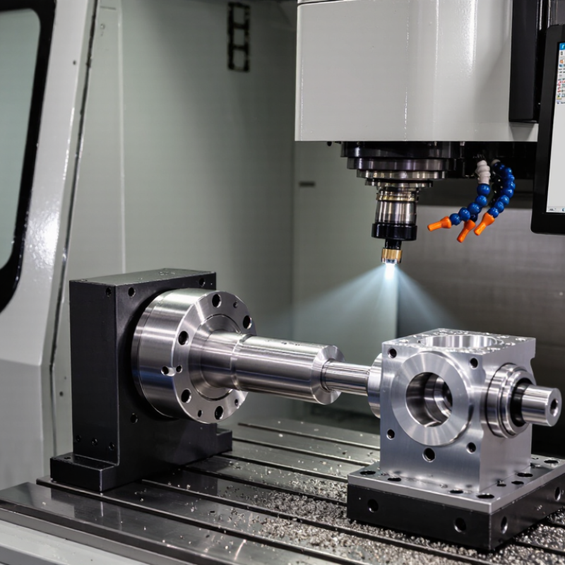
What Is CNC Machining Metal?
CNC machining metal is a subtractive manufacturing process. A computer-controlled machine removes material from a solid metal block. The process follows digital design instructions, often created with CAD and CAM software. Cutting tools rotate, move, and shape the workpiece with controlled precision.
Machines may use three, four, or five axes. More axes can reach complex surfaces with fewer setups. Common metals include aluminum, steel, brass, and titanium. Each material needs suitable cutting speeds, feeds, and tooling. In a workshop, operators also check tool wear, vibration, heat, and chip formation. These details affect surface finish and dimensional accuracy. The finished part still requires inspection. Calipers, micrometers, or coordinate measuring equipment can verify critical features. It is precise work, but not effortless.
Tips: Confirm the drawing’s tolerances before machining. Use rigid workholding to reduce movement. Allow enough material for finishing passes. Sharp tools usually produce cleaner edges. Coolant can control heat, but poor chip removal may still damage a part. A perfect first setup is not guaranteed. Small errors in clamping or tool offsets can change the result. Reviewing the setup before cutting often prevents expensive rework.
CNC machining removes material from a solid workpiece using computer-controlled cutting tools. Material density affects part weight, cutting behavior, tool selection, and machining efficiency. The values shown are typical room-temperature densities in grams per cubic centimeter.
How CNC Machines Cut and Shape Metal
CNC machining cuts and shapes metal through programmed movements. A digital model guides the machine’s cutting tools along carefully calculated paths. The operator secures the metal block, loads the program, and checks the tool setup before cutting begins.
The process can involve milling, turning, drilling, or tapping. During milling, rotating cutters remove material from the workpiece. Turning spins the metal while a fixed tool shapes its diameter. Sharp tools remove thin layers, leaving slots, holes, shoulders, or curved surfaces. Chips fall away as coolant reduces heat and friction. Small details matter.
Accuracy depends on more than software. Tool wear, metal hardness, vibration, and poor workholding can change the final size. A loose clamp may leave marks or create dangerous movement. Experienced machinists measure critical features with calipers, micrometers, or coordinate equipment during production. They also inspect the first part before running more pieces. Even a precise program can produce an imperfect result. That reality deserves attention. Adjustments may involve cutting speed, feed rate, tool offset, or a revised setup. A clean edge often reflects careful preparation rather than faster cutting.
Key Steps in the CNC Metal Machining Process
CNC metal machining begins with a digital model, but the process depends on disciplined preparation. An engineer checks wall thickness, hole sizes, tolerances, and tool access before programming. The CAD file then becomes toolpath instructions through computer-aided manufacturing software. According to the U.S. National Institute of Standards and Technology, better digital coordination can reduce manufacturing errors and improve process traceability. That matters when a small offset can ruin an expensive aluminum billet.
The machine setup follows. An operator secures the metal blank, loads cutting tools, sets the work coordinate system, and verifies tool length. The program is often tested through simulation before cutting starts. Then the spindle removes material through milling, turning, drilling, or boring. Cutting speed, feed rate, coolant flow, and tool wear require constant attention. A 2023 report from the International Federation of Robotics recorded more than 4 million industrial robots operating worldwide, showing how automation is expanding across manufacturing. CNC machining still needs human judgment.
Inspection comes after machining. Operators measure critical features with calipers, micrometers, or coordinate-measuring equipment. They compare results with the engineering drawing and record deviations. A first article may pass, yet later parts can drift as tools wear or heat changes the machine. This is where real experience becomes difficult to replace. The simulation looked perfect. The part did not. Revising offsets, improving fixturing, or changing the cutting sequence may be necessary. The process is precise, but never careless.
| Step | Process Stage | What Happens | Typical Data or Parameters | Common Equipment | Primary Result |
|---|---|---|---|---|---|
| 1 | Design and CAD Modeling | A three-dimensional part model is created with the required dimensions, holes, radii, threads, surface requirements, and material information. | Units: millimeters or inches Geometry: solid model, holes, pockets, slots, and contours Drawing information: dimensions, datums, and tolerances | CAD software and engineering drawings | A digital definition of the metal component |
| 2 | CAM Programming | The CAD model is converted into toolpaths that define how the cutting tool will remove material from the workpiece. | Toolpath types: facing, roughing, finishing, drilling, and threading Cutting data: spindle speed, feed rate, depth of cut, and step-over Output: machine-readable G-code or equivalent numerical-control code | CAM software and post-processor | A verified machining program |
| 3 | Material Selection and Preparation | A metal blank is selected according to strength, corrosion resistance, thermal performance, machinability, and final application requirements. | Common metals: aluminum, steel, stainless steel, brass, copper, and titanium Stock forms: bar, plate, block, tube, or casting Allowance: extra material is retained for machining | Material saw, stock preparation tools, and measuring equipment | A correctly sized and identified workpiece |
| 4 | Workholding and Machine Setup | The workpiece is secured, tools are loaded, and the machine establishes the relationship between the part, cutting tools, and coordinate system. | Setup data: work offset, tool length offset, fixture location, and tool number Important condition: the part must be held rigidly without excessive distortion | CNC mill, CNC lathe, vise, chuck, fixture, probes, and tool holders | A repeatable machining setup |
| 5 | Machine Calibration and Program Verification | The operator checks tool offsets, coordinate directions, program travel, clearance, and possible collisions before cutting the metal. | Checks: dry run, single-block operation, toolpath simulation, and offset verification Safety factors: adequate clearance and correct spindle direction | Control panel, simulation software, probes, and inspection tools | A validated program and safer first operation |
| 6 | Roughing | Larger cutting tools remove most of the unwanted material efficiently, leaving a controlled amount for later finishing operations. | Objective: high material-removal rate Typical strategy: multiple passes with a programmed stock allowance Key controls: cutting load, chip evacuation, coolant, and tool deflection | Carbide end mills, drills, turning tools, and coolant system | A near-net-shape component with machining allowance |
| 7 | Finishing | Smaller or specialized tools perform the final passes to achieve the specified dimensions, geometry, edge condition, and surface finish. | Operations: finish milling, reaming, boring, threading, chamfering, and turning Surface finish: commonly specified using Ra values Dimensional control: depends on machine condition, tool wear, material, and setup | Finish mills, reamers, boring tools, taps, thread mills, and turning tools | A finished part close to its design requirements |
| 8 | In-Process Inspection | Critical features are measured during production so that offsets can be corrected before a dimensional problem affects additional parts. | Measured features: diameter, length, position, flatness, perpendicularity, and surface condition Typical tools: calipers for general checks and micrometers or gauges for closer control | Calipers, micrometers, height gauges, probes, and bore gauges | Early detection of dimensional variation |
| 9 | Deburring and Cleaning | Sharp edges, burrs, chips, and cutting fluid are removed without changing the functional geometry of the component. | Methods: hand deburring, abrasive tools, brushing, washing, or controlled tumbling Requirement: preserve critical edges, holes, threads, and mating surfaces | Deburring tools, brushes, washers, and compressed-air systems | A clean and safe-to-handle part |
| 10 | Final Inspection | The completed part is compared with the engineering drawing or digital inspection plan before release. | Inspection data: dimensional results, geometric tolerances, surface finish, material traceability, and visual condition Typical capability: standard CNC work may achieve approximately ±0.1 mm; tighter values require controlled equipment, tooling, and process conditions | Coordinate-measuring machine, optical comparator, gauges, and surface tester | Documented conformity decision |
| 11 | Optional Post-Processing | Additional treatments may be applied to improve corrosion resistance, hardness, wear resistance, appearance, or dimensional stability. | Examples: anodizing for aluminum, plating, passivation for stainless steel, heat treatment, powder coating, and surface polishing Note: treatment can affect dimensions and should be included in the design plan | Specialized finishing and heat-treatment equipment | Improved functional or cosmetic performance |
| 12 | CNC Process Output | CNC machining produces accurate, repeatable metal parts by controlling tool movement along programmed axes while material is removed. | Common machine types: 3-axis, 4-axis, and 5-axis machining centers; CNC lathes for rotational parts Main variables: axis motion, spindle speed, feed rate, tool geometry, workholding, coolant, and inspection control | CNC machining center or CNC turning center | A repeatable metal component manufactured from digital instructions |
Common Metals Used in CNC Machining
CNC machining turns digital designs into precise metal parts by removing material with computer-controlled cutting tools. The chosen metal strongly affects cutting speed, tool wear, surface finish, and final cost. No material is universally easy to machine.
Aluminum is lightweight and machines quickly, making it useful for housings, brackets, and prototypes. It produces bright chips, but sharp tools help prevent material from sticking to the cutter.
Carbon steel offers strength and predictable performance. However, it can generate heat during heavy cuts, so proper coolant flow matters.
Stainless steel resists corrosion and looks clean, yet it often work-hardens. Slow, careless cutting can make the next pass harder.
Brass machines smoothly and can produce crisp edges with little effort. It suits fittings, small mechanical parts, and decorative components.
Copper conducts heat and electricity well, but its softness may cause burrs or rough edges.
Titanium is strong, light, and corrosion-resistant. It also demands patience, rigid workholding, and careful heat control. It cuts slowly. That choice matters.
Material selection should match the part’s load, environment, tolerance, and production volume. A machinist may inspect chips, listen for vibration, and measure the first part before continuing.
Drawings sometimes underestimate finishing needs. I have found that a technically suitable metal can still create unnecessary problems when its machining behavior is ignored. Testing one sample often reveals more than relying on a material chart alone.
Benefits and Applications of CNC Metal Machining
CNC metal machining uses computer-controlled tools to shape aluminum, steel, titanium, brass, and other alloys. A digital design guides cutting, drilling, turning, or milling operations. The machine follows programmed coordinates with repeatable movement. In practice, the result still depends on tooling, fixturing, material condition, and inspection.
The main benefit is consistency. A properly prepared process can produce dozens of parts with nearly identical dimensions. This helps manufacturers control assembly fit and reduce manual rework. CNC machining also supports complex curves, narrow slots, threaded holes, and internal features. Operators can adjust cutting speed and tool paths for different metals. Short setup times can make small production runs practical. Fast changes matter.
Applications cover many demanding fields. Machined metal parts appear in industrial equipment, robotics, transportation systems, energy hardware, and laboratory instruments. Engineers often use CNC machining for prototypes because design changes can move from a computer model to a physical part quickly. It also suits custom brackets, shafts, housings, molds, and replacement components. Careful inspection remains essential, especially where tight tolerances affect safety or performance.
CNC machining is not effortless. A misplaced zero point can spoil an entire batch. Tool wear may leave rough edges or inaccurate holes. Heat can also change dimensions during cutting. These limits deserve attention when estimating cost, lead time, and material waste. A skilled operator checks the first part, measures critical features, and refines the process before wider production.
