
How to Choose a Compact UAV BMS for Your Drone?
Choosing a compact UAV BMS is a practical engineering decision, not a simple size comparison. A drone battery system must fit a narrow frame, manage changing loads, and protect cells during demanding flights. Even a few extra grams can affect endurance, balance, and motor response. Small details matter here.
An experienced selection process begins with battery chemistry, cell count, continuous current, and peak current requirements. Check whether the BMS supports accurate voltage measurement and reliable temperature sensing. Look for balanced charging, overcurrent protection, short-circuit response, and clear fault reporting. Communication options also deserve attention. CAN, UART, or another interface should match the flight controller and ground-support equipment. A compact board may look suitable, yet weak connectors can create trouble under vibration.
Thermal performance is easy to underestimate. A BMS mounted beside warm power electronics may need airflow, insulation, or a different installation position. Review datasheets, test reports, and manufacturer support before making a final choice. Bench tests should include startup current, repeated acceleration, low-battery conditions, and temperature changes. Field experience helps, but it is not enough alone. One early mistake is choosing the lightest unit without checking peak load behavior. That shortcut can produce unstable readings or unexpected protection events. It may also waste more time than it saves. A reliable Compact Uav Bms should balance weight, safety, communication, serviceability, and verified performance. No single specification decides everything. The best choice fits the whole aircraft.
UAV BMS Fundamentals for Compact Drone Power Systems
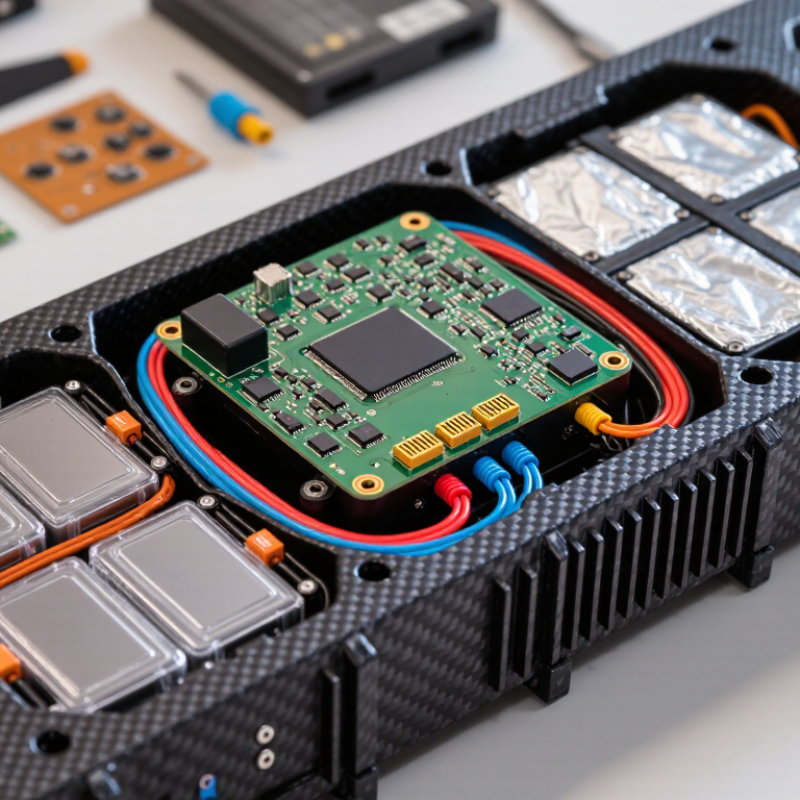
A compact UAV battery management system (BMS) monitors cell voltage, pack current, and temperature while protecting the battery from unsafe operating conditions. In a small airframe, every gram and cubic centimeter matters. Yet reducing the BMS to the smallest possible board can leave too little room for heat dissipation, wiring clearance, or reliable sensing. Small does not mean simple.
Cell-level voltage readings help identify imbalance that a pack-level measurement might hide. Passive balancing can gradually reduce small differences between cells, usually during charging, but it cannot repair a worn or damaged cell. Temperature sensors should sit where heat is likely to build, such as near the pack’s central cells. One sensor in the wrong place may create false confidence. That detail is easy to overlook.
Current measurement supports power estimates and helps the controller detect overloads. For a drone, rapid changes in motor demand make response time important. The BMS should communicate useful warnings, including low voltage, excessive temperature, and sensor faults, without flooding the flight controller with noise. Protection thresholds must match the battery chemistry and the manufacturer’s specifications; copying values from another pack is not a sound shortcut.
Designers should check the complete assembly, not only the circuit board. Connectors, cable length, vibration, and airflow all affect performance. Bench testing can reveal voltage errors, while controlled flight tests show how readings behave under changing loads. No compact system removes uncertainty. Measure, document, and revisit the assumptions.
| Selection Dimension | Typical Values or Options | What to Check for a Compact Drone |
|---|---|---|
| Battery chemistry | Lithium-ion and lithium-polymer (LiPo) cells are common in rechargeable UAV battery packs. | Confirm that the BMS supports the exact cell chemistry and its specified charge and discharge voltage limits. Do not assume that voltage limits are interchangeable between chemistries. |
| Series cell count | Small UAV packs commonly use 3S to 6S configurations. A 3S pack has three cells in series; a 6S pack has six. | Match the BMS to the pack's series count. For standard LiPo cells rated at 3.7 V nominal and 4.2 V maximum per cell, a 4S pack is 14.8 V nominal and 16.8 V at full charge. |
| Cell voltage limits | For many standard Li-ion and LiPo cells, 4.2 V per cell is the full-charge voltage. The permitted lower voltage depends on the cell specification and application. | Set overvoltage and undervoltage protection to the cell manufacturer's limits. Avoid selecting thresholds from a generic pack voltage alone. |
| Continuous discharge current | Required current depends on the propulsion system, payload, flight profile, and battery voltage; there is no single current rating suitable for every UAV. | Size the BMS for the pack's expected continuous load, with allowance for operating conditions. Verify that the cells, wiring, connectors, and BMS can all support the same current. |
| Peak discharge current | Motor acceleration and rapid load changes can produce short-duration current peaks above the steady-state load. | Check the BMS peak-current rating and its permitted duration. Compare it with measured or specified propulsion-system peaks, not just the average flight current. |
| Charge current | The safe charge current is determined by the cell and pack specifications; the BMS may impose an additional limit. | Choose a BMS compatible with the charger and the pack's permitted charge current. Confirm whether charging is allowed through the same terminals used for discharge. |
| Cell balancing | Passive balancing dissipates energy from higher-voltage cells; active balancing transfers energy between cells. | Confirm that the BMS balances every series cell and supports the pack's chemistry and voltage range. For compact designs, compare balancing current, heat generation, and board area. |
| Protection functions | Common functions include cell overvoltage, undervoltage, overcurrent, short-circuit, and temperature protection. | Check protection thresholds, response behavior, recovery conditions, and whether faults can be reported to the flight controller or battery monitor. |
| Temperature monitoring | Temperature sensing may use one or more thermistors placed near cells or power components. | Verify sensor count, supported sensor type, placement requirements, and charge/discharge temperature limits specified for the cells. |
| Telemetry and interface | Options may include a simple voltage/current output or digital communication interfaces such as UART, I²C, or CAN. | Match the interface and data format to the flight controller or ground-system requirements. Check which values are available, such as pack voltage, current, temperature, and state of charge. |
| Size and mass | Board dimensions and mass vary with current rating, protection components, connectors, and sensing features. | Compare the complete installed footprint, including connectors, cables, insulation, and required clearance. Confirm that the BMS does not obstruct airflow or interfere with vibration isolation. |
| Thermal design | Power losses increase with current and depend on components, board layout, and cooling conditions. | Review thermal limits at the expected peak and continuous loads. A compact enclosure can restrict heat dissipation, so validate performance in the intended installation. |
| Wiring and connectors | Pack wiring must accommodate the electrical current and cell-sense connections required by the BMS. | Check wire gauge, connector ratings, polarity, strain relief, and cell-tap order. Incorrect cell-sense wiring can damage the BMS or create a safety hazard. |
| Verification before flight | Useful checks include cell-voltage balance, protection behavior, current measurement, telemetry, and thermal operation. | Test the assembled battery system using suitable equipment and a controlled procedure before flight. Follow the battery, charger, and BMS documentation. |